


HIC004-2 Scan Add-On Tool
HIC004-2 Scan Add-On Tool
The HIC004-2 Scan Add-On Tool not only acts as a Protocol Detector & Break Out Box to DLC (Diagnostic Link Connector), it also has a voltage monitoring feature with Volts display, which will give an alarm warning when the voltage falls below 12.0Volts or higher than 15.2Volts.
With the Voltmeter display, you are able to monitor the voltages while doing programming or coding, giving an alarm when the voltage falls below 12V or rises above 15.2V. This feature will minimize any error while performing service reflashes.
The unit has has coloured LEDs that light up to display protocol detected, grounds, and voltage. It serves as
- DLC magnifier (makes DLC 5 times larger)
- DLC extender (place DLC where you need it)
- SPY (you can monitor the activity on each OBDII dedicated data line)
You can also check the Alternator charging conditions by referring to the displayed voltages during electrical loading at 2000rpm and unloading at 3000rpm while plugged into the DLC socket.
New Updated Feature - self test function for OBD port
This unit when first plugged into the OBD diagnostic socket will perform a self test on all the 16pins of the diagnostic socket to make sure it is safe to plug your scan tool into.
How to Use:
-
Switch the ignition key to OFF position.
Connect the Scan Add-On Tool to the DLC on vehicle. Turn ignition key back to ON position.
As soon as it powers up, the voltmeter will display the battery volts and automatically checks the power, grounds, DLC data wires and searches for voltage pulses. -
As Power source:
While connected to the car DLC, you can tap +12V at the red banana socket (pin 16) and Chassis Ground (-) at black banana socket (pin 4) to power other DC loads. Capacity rated at 5 Amps. -
Detecting Protocol in use:
Plug your scan tool or interface to Scan Add-On Tool. Use the scan tool to view live data stream. Check the flashing blue LEDs and match them with the protocols marked on the label -
Check Alternator charging condition:
With ignition key in OFF position, plug Scan Add-On Tool into the car DLC. Switch key to ON position and the tool will display the battery voltage. Start the engine; observe the voltage display while the engine is idling. It should be above 12.6 Volts. If not, check for loose drive belt.
Then rev engine up to 3,000rpm and observe the change in voltage. If the voltage is above 15.2 Volts, the alarm will beep indicating that the charging voltage is too high. In this case, the regulator needs to be checked.Then switch ON all electrical loads, rev engine to 2,000rpm and observe the changes in voltage at the tool. The voltage should above 13.6 Volts. If the voltage is below, check for loose drive belt and the Alternator.
Some Typical Applications:
- VW - To protect the Scan tool such as aftermarket radios on VW's
- GM - Transmitter Programming on some GMs
- Honda - Set the ECM in SCS mode with your scan tool connected
- Lexus - Help diagnose electronics systems (Sirius, GPS) on pin 6 and 14
- Bosch - Troubleshoot Bosch controllers that short to ground
Features:
- Constantly monitor Battery Voltage with volts display and warning beeps for Low (Below 12V) and High (Above 15.2V) an important feature for ECU programming, reflash and coding operations.
- OBDII Breakout points with Protocol and data signal detection shown by flashing color LEDs to indicate the functionality of the ECU when in operation with a Scan tool.
- Provides quick check on Alternator charging conditions.
- Power source for other DC loads up to 5 Amps DC output at pin 4 and 16 socket.
- Its standard 4 mm female banana jack receptacles accept both standard and sheathed male banana plugs.
- Protected by a self- healing fuse rated at 5 amps.
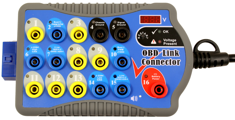
LEDs Activity:
OBDII Protocol Detector & Breakout Box LEDs allows you to keep tabs on power and ground. It identifies the protocol used in the vehicle.
RED LEDs
(Pin 16) - automatically turn-on as soon as you plugged into DLC.
RED LEDs turn dim when:
- Low battery voltage - refer to Voltmeter and alarm will beep (below 12V)
- Wiring to DLC pin 16 is faulty
- Grounds circuits has resistance issues
GREEN LEDs
(Pins 4 and 5) - automatically turn-on as soon as you plugged into DLC. Ground LEDs (Pin 4 and 5) is connected to battery voltage through pin 16. Therefore, a ground supply on pin 4 will not affect LED 5. A dim single green LED will indicate a circuit problem with the corresponding circuit.
BLUE LEDs
(Pins 2, 6, 7 and 10) - LEDs should flash when serial data voltage pulses are present in the data line. Blue LEDs is assigned on pins 2, 6, 7 and 10 to indicate communication with scan tool or interface and for communication protocol identification. It will turn-on depending on your vehicle model. For some vehicle models, none or multiple blue LEDs will turn-on as soon as the Breakout Box is connected and you start the ignition.
The brightness of the LEDs depends on the nature of the signal it's pursuing. The Breakout Box can indentify immediately the protocol used. The better way to indentify the protocol in use is to set-up the scan tool or interface in to LIVE DATA. This will lead in a constant data stream between the scan tool and the vehicle, and then you can locate the LEDs that are flashing.
YELLOW LEDs
(Pins 1, 3, 8, 9, 11, 12, and 13) - it should flash when your vehicle manufacturer uses either one on the pins for any function they prefer.
Pin Assignments
| Pin No. | SAE Designation |
|---|---|
1 |
Discretionary |
| 2 | Bus + Line of SAE J1850 (PWM/VPW) |
| 3 | Discretionary |
| 4 | Chassis Ground |
| 5 | Signal Ground |
| 6 | CAN High of SAE J2284 (ISO 15765-4) |
| 7 | K Line of ISO 9141-2 and ISO 14230-4 |
| 8 | Discretionary |
| 9 | Discretionary |
| 10 | Bus-Line of SAE J1850 (PWM) |
| 11 | Discretionary |
| 12 | Discretionary |
| 13 | Discretionary |
| 14 | CAN Low of SAE J2284 (ISO 15765-4) |
| 15 | L Line of ISO 9141-2 and ISO 14230-4 |
| 16 | Unswitched Vehicle Battery Positive |
Pins listed as "Discretionary" indicate that the vehicle manufacturers may use them for specified purpose. Check with the manufacturer's specifications for these connections.
For voltage and current limits, refer to SAE J1962 (ISO 15031-3.3). Test tool must not draw more than 1.5 amps through the pin number 5.
Helpful Tips:
When activating some ABS and diagnostics wires to recover flash code, you can use pin 4 or pin 5. To power small DC loads with maximum 5 Amps you can use pin 16.
If red (power) and green (grounds) LEDs turned dim or flickering when you plugged a scan tool supplied via DLC, it indicate a problem with your vehicle wiring that causes the voltage to drop.
Product Specifications
| Operating range: | 7.0 ~ 20.0VDC Input. |
| Maximum Load: | Up to 5.0 Amps. Output. |
| Overload Protection: | Yes- PTC Fuse (Self-healing) |
| Monitoring Voltages: | Below 12V beeper ON; Higher than 15.2V beeper ON. |
| Volt Displays: | 3 Digits LEDs (Resolution: 0.1V) |
| Banana Sockets: | 16 outputs x 4.0mm diameter with LED lamp indications. |
| Protocols Detected: | PWM (J1850), VPW (J1850), ISO 9141-2, DIS/ISO 14230-4, Canbus (J-2284). |
| OBDII connection: | Total including tool: 88mm length. |
| Operating temperature: | 0 Deg.C ~ 50 Deg.C (32 Deg.F~122 Deg.F) |
| Permitted Humidity: | Less than 70%. |
| Reverse Polarity protection: | Yes with LED lights up when in correct polarity. |